Background:
This grinding wheel was part of a product liability and personnel injury case. It was claimed that the subject wheel had unexpectedly failed (i.e. flown apart) and an escaping piece had hit the plaintiff in the face causing serious injuries. According to the user, the grinder with the wheel was purchased approximately one hour before the grinding wheel failure. In addition, the user claimed that the grinder was being used as recommended by the manufacturer. Thus, it was claimed that the wheel was properly mounted and the guard was in place.
Summary:
A root cause failure analysis determined that the subject grinder had been abused by the plaintiff. In addition, the subject grinding wheel had been broken in a clamp such as a vice. The subject wheel did not fly apart and injure the plaintiff. It is believed that he was injured by an event that did not include the grinder being properly used. The accident could not have happened as the plaintiff had described it.
Grinder Inspection:
The subject hand tool (i.e. grinder) and failed grinding wheel were inspected to determine the facts surrounding the grinding wheel failure and to determine the cause of the personal injury. Figure #1 is a photograph of the subject grinder along with the wheel purported to have spontaneously broken and to have caused a personal injury. In this photograph the grinder is assembled with the guard. Figure #2 is a side view of the grinder. The wheel is properly mounted with the guard in place. The edge of the cup shaped grinding wheel has at least 3/4" clearance from the grinder body. Also, the guard is interposed between the grinding wheel and the grinder body. It is evident that the subject wheel is completely isolated from the grinder body. Thus, when properly mounted and used, the wheel cannot damage the grinder body. Figure #3 is shows the subject grinder. There is significant visible damage to the grinder body. There are two areas of circular grind damage. One is at a diameter of 3" the other is at a diameter of 9". Both sets of damage are centered on the grinder's drive shaft; therefore, this damage was caused by an abrasive wheel rotating on the grinder's spinle. None of this damaged could have been caused by the 4-1/2" cupped grinding wheel supplied with the grinder, or could it have happened with the guard properly mounted.
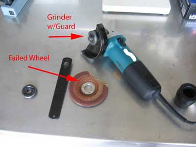
Figure #1 is a photograph of the subject failed grinding wheel and the subject grinder. The grinder is assembled with the guard.
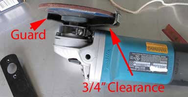
Figure #2: Side view of the subject grinder with the grinding wheel and guard properly mounted. The mounting system (i.e. with the guard and mounting flanges) creates a 3/4" gap between the wheel and the grinder body. In addition, the guard is between the wheel and the grinder body. Therefore, in this condition, the wheel cannot damage the grinder body.
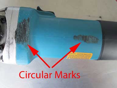
Figure #3: Photograph of the subject grinder. There is significant visible grind damage to the grinder body. There are two areas of circular grind damage. One is centered at a diameter of 3" the other is centered at a diameter of 9". Both sets of damage are centered on the grinder's spindle; therefore, this damage was caused by an abrasive wheel rotating on the grinder's shaft.
Grinding Wheel Failure Analysis:
Figure #4 is a photograph of the subject "failed" grinding wheel. The grinding wheel is a fiber reinforced resin bonded wheel. Looking at the paper along the edge of the failure, one can see that it is folded over. This would not have occurred if the wheel had "flown apart" as claimed. In addition, there is a linear set of tool marks more or less opposite the failure. These marks indicate that this wheel had been held in a clamp. Thus, its condition had been altered after it had been sold. Figures 5 & 6 show these marks in more detail, From this evidence, one must conclude that the subject wheel had been clamped in a device such as a vice and that the missing piece had been purposely broken off by forcefully bending the clamped wheel.
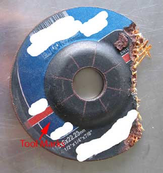
Figure #4 is a photograph of the subject "failed" wheel. Along the fracture the paper label is folded over. In addition, there is a set of linear tool marks that are indicated by the arrow.
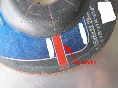
Figure #5 is a close up photograph of the subject "failed" wheel. The set of linear tool marks are more visible. These marks indicate that this wheel was held in a clamp (probably a vice).
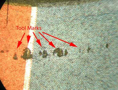
Figure #6: Low power photomicrograph of the tool marks. They are in a linear array and are seen because the paper label has been penetrated by a clamp. Damage to the paper label made it possible to see that the wheel had been clamped and was not in the "as sold" condition (Mag. 15X).
Dr. Thomas L. Read, CEO of Read Consulting received his PhD. from Stanford University in 1972. He has over 25 years of manufacturing experience in electronics, metallurgy, factory safety, failure analysis, glass fracture, glass failure and bottle failure. As a member of the electronics industry, Dr. Read has earned process patents and has an extensive background in manufacturing techniques. In parallel, he has spent over twenty five years as a consultant to attorneys and engineers in the areas of failure analysis, metallurgy, glass fracture, glass failure, bottle failure, factory safety, manufacturing problems, intellectual property and patent disputes.
©Copyright - All Rights Reserved
DO NOT REPRODUCE WITHOUT WRITTEN PERMISSION BY AUTHOR.