Introduction: This ceramic tank failed in a second floor bathroom and caused extensive water damage to a home. Read Consulting was engaged to determine the cause of failure.
Inspections
The cracked tank was first inspected in the "as received" condition. In this condition it was cracked, but it was still whole. Next, the failed tank was separated by pulling it apart. This was done to expose the fracture surfaces of the main crack. This allowed for a complete failure analysis and for a determination of where the crack initiated.
Description of the Evidence Available for both inspection were the failed tank and some of the hardware. The hardware includes the handle, the "flapper" mechanism, the top half of the two hold down bolts and some of the hardware used to hold the toilet to the flange on the floor. An overview of the as received tank is shown in Figure #1. Because the main crack had stopped, the tank remained whole, and this prevented a complete failure analysis. Before the failure analysis could be performed, the two halves of the tank needed to be separated. Some observations were made of the tank bottom and hardware and these are listed below; they are also illustrated by Figure #'s 1 to 3.
- It appears as if a hacksaw was used to cut the two hold down bolts.
- There was a piece of rubber pinched in the main crack on the right side of the drain hole.
- There is evidence that a metal washer had damaged the bottom of the tank around the right side bolt hole. This indicates that this toilet was assembled with a nut and washer on the underside of the tank. This is not normally done.
- There are several other cracks (unfinished) around the drain hole.
- There are staining and chipping around the the right side bolt hole.
- Both hold down bolts have what appear to be calcium deposits. This indicates that there were leaks occurring at both hold down locations.
Note: The presence of washer damage on the outer bottom of the tank indicates that an attempt was made to stop the leaking by trying to squeeze the inner rubber washer assembly with an external nut and washer.
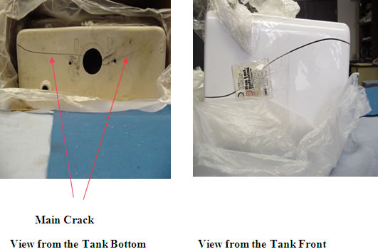
Figure #1: Two views of the failed tank. The main crack runs from the top of the tank on the right side (in a frontal view) across the bottom and partially up the left side. This crack also ran through the hole for the right hold down bolt and through the large "drain" hole in the center of the tank. Because the tank was still intact, the fracture surfaces were hidden, and a complete failure analysis could not be performed.
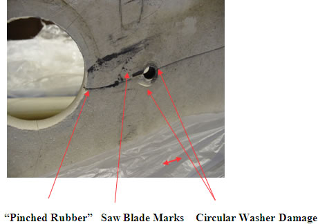
Figure #2: Close-up of the right bolt hole and right side of the drain hole.
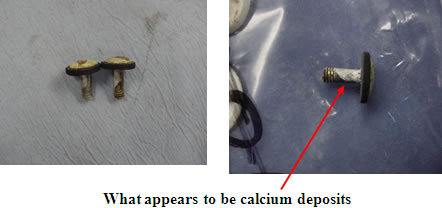
Figure #3: Photograph of what remains of the two hold down bolts. Both appear to have calcium deposits on them. This indicates that the holes were leaking.
Completion of the Failure Analysis
The tank was pulled apart for this part of the inspection. This exposed the two fracture surfaces. Below are photographs of the discoveries made during this inspection.
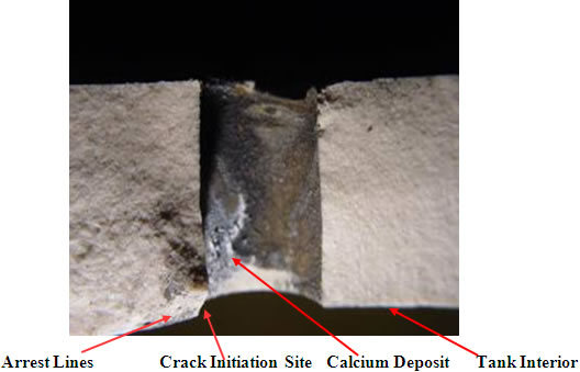
Figure #4: One view of the fracture surfaces at the right hand hold down hole. For this photo the light angle was chosen to reveal a series of crack arrest lines from a crack starting on the inside of the tank. These are on the right side of the hole. In addition, there is staining in this region. This indicates that this initial crack existed long before the failure (growth of mold and bacteria). These lines indicate that this crack initiated at the site indicated.
Note: A crack arrest line is formed when a crack stops then starts up later. The stress that re-starts the crack is in a slightly different direction; so, during the re-start the crack changes direction and forms the line. In addition, the stresses that are driving the crack are applied stresses; they are not residual stresses from manufacturing.
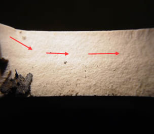
Figure #5: Fracture surface near the drain hole. The piece of pinched rubber is shown. In addition, there is no staining. The arrows show the travel direction of the crack. Note: The markings that indicated the crack travel direction are very faint. This crack started on the inside of the tank at the edge of the holes.
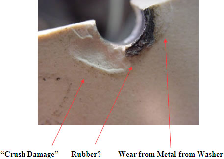
Figure #6: Close up of the damage around the right side hole for the hold down bolt. This damage consists of crushing and digging in from a washer tightened against the bottom of the tank. In addition, there is evidence that part of a rubber washer was present.
Results
The failure initiated first at the hole for the right hand hold down bolt. The final failure initiated at the right hand hold down bolt and at the center "drain" hole. The presence of the arrest lines indicate that the failure was caused by applied stresses. If it were the result of manufacturing stresses, the crack would have gone to completion once it was initiated.
Discussion
This tank was in service for over 13 years. In addition, it shows evidence that there were long term cracks and leaks. It is my opinion that this tank has seen a lot of "wear and tear". In addition, the evidence of damage around the hold down holes on the outside of the tank indicates that this toilet was not assembled according to the manufacturer�s instructions. It appears that there were a nut and washer screwed up against the bottom of the tank. Also, there are signs that this assembly was over tightened. This tank failed as a result of handling damage; it didn't fail from manufacturing stresses.
Dr. Thomas L. Read Dr. Thomas L. Read, CEO of Read Consulting received his PhD. from Stanford University in 1972. He has over 25 years of manufacturing experience in electronics, metallurgy, factory safety, failure analysis, glass fracture, glass failure and bottle failure. As a member of the electronics industry, Dr. Read has earned process patents and has an extensive background in manufacturing techniques. In parallel, he has spent over twenty five years as a consultant to attorneys and engineers in the areas of failure analysis, metallurgy, glass fracture, glass failure, bottle failure, factory safety, manufacturing problems, intellectual property and patent disputes.
See Dr. Read's Profile on Experts.com.
©Copyright 2005 - All Rights Reserved
DO NOT REPRODUCE WITHOUT WRITTEN PERMISSION BY AUTHOR.