During start-up trials of a group of large hydro turbine generators, Mechanical Solutions, Inc. (MSI) was called on behalf of a hydroelectric power company to support them in their lawsuit against a well-known manufacturer. The generator functioned with only minor flaws in all seven of the large units, but the Francis turbines developed unacceptable vibration levels when operating in the lower portion of the contract range in their power vs. flow rate Hill Chart.
The legal question centered on comparison of the contract technical specifications versus industry standards such as ISO 20816-5 for hydro turbine vibration, which MSI engineers had helped to author.
The technical aspect was whether the units not only vibrated more than allowed by acceptance standards, but whether this level of vibration was actually causing damage. If damage was occurring, the source of the vibration needed to be identified, and a permanent and appropriate fix needed to be designed, one that would not take the units out of service for an extended period of time. Finally, responsibility for the problem needed to be assigned, and the costs determined to be associated with any remediation.
MSI carefully reviewed the extensive test data available from the site, and proved that there were two problems present in the design of the turbine, one mechanical and one hydraulic. Mechanically, the rotor system’s second critical speed was well damped, but was within several percent of the running speed, leading to mild resonance. This increased vibration levels at 1 x rpm, but was not the primary reason for the violation of vibration standards at low loads. The main contribution to vibration was not at running speed (i.e “asynchronous”) and not at any running speed integer harmonic, suggesting a fluid dynamic (hydraulic) issue.
MSI performed a rotordynamics analysis that confirmed that the rotor natural frequency was too close to running speed, but would be difficult to move out of its mild resonance, requiring extensive bearing support modifications to fix. Therefore, fixing this was not considered a practical option, or necessary.
An extensive computational fluid dynamics analysis was then performed by MSI, modeling the entire flow system, from the headwater at the dam to the tailwater in the downstream river. This included all of the internals of the turbine inlet, wicket gates, runner with its rotating blade passages, draft tube with splitter, and tailwater, as shown in the model cross-section and model perspective view in Figure 1. To not miss any important physics, the rate of flow change in the model was set at millionths of a second, as the runner turned.
Figure 1: Cross-section (top) and 3-D meshed perspective view of the hydroturbine system CFD model
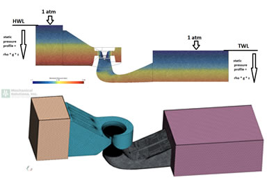
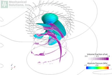
Figure 2 shows some key results of the unsteady (transient) analysis including two-phase flow with cavitation simulated. The left picture shows flow re-circulation unexpectedly BACKWARDS through the runner at low power levels. This situation led to a tangential velocity field and associated radial forces rotating at asynchronous frequencies, as shown in the picture at the right. The shaking forces and frequencies matched well with the plant operational data. Most importantly, the CFD demonstrated not just the nature of the problem, but that it was definitively a design deficiency. The analysis also suggested a practical fix, for which quantitative mediation costs could be calculated.
Figure 2: Results from CFD analysis of the hydroturbine flow path at low power conditions

Figure 3 shows how air injection was able to be implemented in the runner hub. The CFD demonstrated that only one percent air injection was required
to break up the re-circulating flow at low power, and eliminate the asynchronous forces on the rotor, solving the vibration problem. This fix required minimal modification of an existing option for air injection, and its cost was within the feasible range of financial award in this case.
MSI then participated as a key expert witness in court, in which they explained the credibility and import of the results. At the conclusion of the case, the utility won, and received an award of tens of millions of dollars. This paid for all required remediation, enabling a large amount of renewable energy to be reliably added to the North American electrical grid.
Figure 3: Results from CFD analysis showing air injection distribution at low power condition, breaking up the previous re-circulating backflow.