Mechanical Solutions, Inc. (MSI) was contracted by the international OEM to perform testing and analysis to determine the root cause of gear tooth failures on an aeroderivative gas turbine power generation drivetrain. The 40 MW gearbox had broken pinion teeth after several thousand operating hours. The OEM was proceeding with a tooth profile re-design to make the gear more tolerant of the misalignment concerning which other consultants had attributed the tooth failures. However, the failures continued. The OEM concluded that the postulated level of gear mesh misalignment could not explain the tooth failures, but the true cause remained a mystery. The situation became complicated when the utility operating the “peaker” power units was threatening an EU lawsuit in the Hague.
MSI’s testing consisted of structural and rotor vibration measurements as well as measurement of the gearbox bearing housing deflection with increasing load and temperature. The gearbox structural vibrations at the various load conditions were uneventful, not providing much insight into root cause of the gear tooth failures. The pinion rotor however was measured to behave in an unexpected manner when fully warmed-up. The pinion centerline (average location, not vibration) moved with increasing load as shown by the arrow in Figure 1. It is important to note that the two ends of the pinion behaved very differently with the turbine end following a crescent shaped trajectory and the generator end moving towards the bearing centerline as the load was increased.
In the absence of external forces, a double helical gear will move axially until the torque load is balanced between the two helices. The symmetry of the gears results in identical radial loads on each side which must be carried by each bearing straddling the pinion. Symmetric loading should lead to both bearings behaving in a similar manner- but this was not the case!
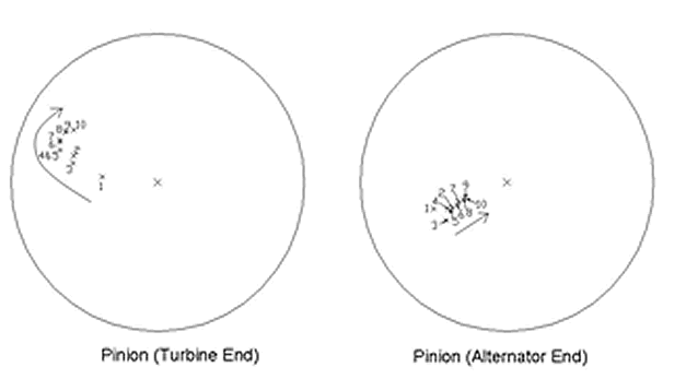
Figure 1: Shaft centerline position relative to the bearing centerline. The outer circle represents the bearing clearance. The arrows indicate the direction the rotor centerline moves with increasing load, represented by the numbers 1 through 10.
The rotor centerline trajectories which were measured indicated an increasing radial load on the turbine end bearing and a decreasing load on the generator end bearing with increasing transmitted torque. In order for this to exist, the external forces must act on the pinion rotor in a manner which results in one of the helices carrying significantly more load. Figure 2 is a free-body diagram of the helical gearset illustrating how the loading on one of the helices can be significantly higher than the other when an external axial force is applied to the pinion.
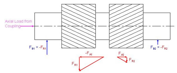
Figure 2: Free Body Diagram of Forces Acting on the Pinion
An external axial force which is transmitted to the pinion must come through the coupling between the turbine and the gearbox, but this was a disk pack coupling which was designed to be flexible in the axial direction, although this was only true for a limited amount of axial travel of the rotors. Starting with this clue, MSI determined that the root cause of the entire problem was that the axial thermal growth of the drivetrain (particularly the turbine’s hot rotor) was greater than the axial travel allowed by the flexible coupling, given the “cold-offset” clearance the plant’s personnel had been (incorrectly) using.
The problem was corrected by simply increasing the axial travel of the coupling between the power turbine and the pinion. The (very expensive) route which the OEM had been taking to redesign the gear tooth profile to account for a hypothetical gear mesh misalignment would not have solved the problem, and may have even resulted in higher tooth stress levels and more frequent failures. In any event, the problem was solved, and a sticky lawsuit was avoided!
Mechanical Solutions, Inc. (MSI), performs litigation support through its extensive engineering capabilities, and when required, through expert testimony. MSI uses advanced finite element analysis (FEA), rotor dynamics, and torsional analysis tools, and uses computational fluid dynamics (CFD) to analyze 3-D steady or unsteady fluid flows and heat transfer, enabled by its 230 high speed processor supercomputers. Its areas of expertise range from new equipment design and forensic analysis to hydraulic turbine generators and aircraft gas turbine engines.
©Copyright - All Rights Reserved
DO NOT REPRODUCE WITHOUT WRITTEN PERMISSION BY AUTHOR.