Introduction
Glass Failure Analysis Expert Witness performs a failure analysis of a several tempered glass doors that had "spontaneously" failed at a construction site. The objective of this glass failure analysis is to determine the cause of failure and make recommendations to the contractor.
Strategy
Randomly select two of the failed doors and perform a detailed failure analysis. If these two failures show common cause, then they are representative of the entire lot of tempered doors.
Procedure
Sample Preservation: The approximate location of the failure origin was located. Next, a 12inch square with the origin in the center was taped with a pressure sensitive tape. Once the 12 inch square of glass was secured, it was removed from the window. This was then transported to the laboratory for the failure analysis.
Removing the Origin: At the laboratory, the exact location of the origin was determined, the tape was removed from this location, and the critical four pieces were removed.
Optical Microscopic Examination: Optical microscopy was used to examine the fracture surfaces to find the origin.
Scanning Electron Microscope (SEM) with Energy Dispersion Spectroscopy (EDS): A SEM with EDS was used to document the origin and to determine the elemental chemistry of the origin.
Results
Figure #1 shows a preserved 12 inch square from one of the two windows examined. The potential failure origin is approximately centered on the square. Figure #2 is a close up photograph of the origin. Its shape is that of the outline of a butterfly. The pieces removed for microscopic examination are labeled. The backside tape was cut from these three pieces and they were removed so that their fracture surfaces could be examined optical microscopy. Figure #3 is an optical photomicrograph taken of the part of the fracture surface that includes the origin. Figure #4 is another optical photomicrograph taken of the part of the fracture surface that includes the origin. In this case the surface has been sputtered with gold, and the Wallner lines are more visible. The Wallner lines clearly show that the crack is spreading out form the center of this piece of the fracture surface. This clearly indicates that this is the origin. Figure #'s 5 through show that the failure is caused by a spherical NiS particle. This was the common mode of failure for the two doors examined.
 Figure #1: Photograph of the 12 inch square preserved from one of the two windows examined. The potential failure origin is approximately centered on the square.
 Figure #2: Close up photograph of the origin. It is at the center of the spreading radial cracks, and it has the appearance of the outline of a butterfly. The four pieces removed for further examination are labeled A, B, C & D.
 Figure #3: Optical photomicrograph taken of the fracture surface, and it includes the origin. At this magnification the origin is a small spec. It is located by tracing the Wallner lines backwards (Mag 8X)
 Figure #4: Another optical photomicrograph taken of the fracture surface at the origin. At this magnification the origin is a still a small spec. This is photograph was taken after gold had been sputtered on the surface. This made the Wallner lines more visible. One can see that the Wallner lines are emanating from the center of this piece of the fracture surface (Mag 20X)
 Figure #5: Higher power optical photomicrograph of the origin shown above using Nomarski Interference Contrast (NIC). At the origin is a 180 micron spherical particle. This is the cause of the failure (Mag 200X).
 Figure #6: SEM photomicrograph of the 180 micron spherical particle shown in Figure #5 (Mag 500X).
 Figure #7: Elemental composition of the spherical particle determined with EDS. The elements present are Nickel (Ni) and Sulfur (S). The particle is a nickel sulfide (NiS) particle.
Results
Both tempered doors failures were caused by spherical NiS contaminant particles. One particle has a diameter of 180 microns. The other particle has a 100 micron diameter. In addition, both particles were centered 2.3 mm from the edge of the glass. This failure mechanism is well known and has been previously documented. The NiS particle forms during glass manufacturing. It is created by contamination in the fuel (S) and nickel from tools used to handle the hot glass. Initially it is one crystal structure; however, over time it will change to a less dense crystal structure that creates local stresses and cracking. The rate of occurrence varies with respect to the manufacturer. NiS contaminants are said to be a problem with fully tempered glass. It is believed that heat strengthened glass does not fail as a result of NiS particles. It is believed that NiS particles are present in heat strengthened glass, but they cannot cause failure.
Procedure
- On site, locate the general region of the failure origins.
- Remove and preserve 12" square pieces around each origin.
- Examine and document the 12" square pieces visually and with a Low Power Microscope.
- Remove the pieces suspected of containing the origin, one piece at a time, and with optical microscopy (low power and high power), examine and document the fracture surfaces at the origin.
- Using a scanning electron microscope, examine and document the fracture origin and any contaminants. If there is a contaminant at the fracture origin, use energy dispersive spectroscopy to determine the major elements of the contaminant.
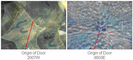 Figure #1: Macro-photographs of the as received glass near the origin. In both cases the origin lies between the two halves of the "butterfly".
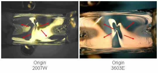 Figure #2: Photo-micrographs of the fracture surfaces near the two origins. These micrographs show Wallner lines emanating from one spot. This identifies this spot as the failure origin (Mag 8X)
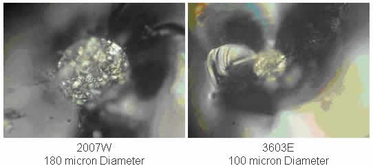 Figure #3: Photo-micrographs taken at the fracture origins. These micrographs show that both failures originate at a spherical contaminant (Approximate Mag 250X).
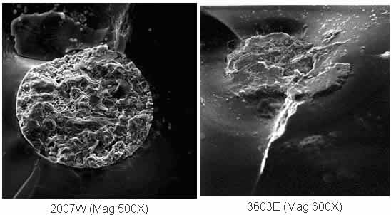 Figure #4: Scanning Electron Microscope Photo-micrographs of each particle at the fracture origin.
Figure #3: Photo-micrographs taken at the fracture origins. These micrographs show that both failures originate at a spherical contaminant (Approximate Mag 250X).
Figure #4: Scanning Electron Microscope Photo-micrographs of each particle at the fracture origin.
Figure #3: Photo-micrographs taken at the fracture origins. These micrographs show that both failures originate at a spherical contaminant (Approximate Mag 250X).
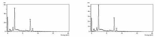 Figure #5: Energy Dispersive Spectroscopy (EDS) data of the two spherical particles at the origins of the two failures. Both particles are nickel sulfide (NiS). That is, these particles consist of the elements of nickel and sulfur.
Dr. Thomas L. Read, CEO of Read Consulting received his PhD. from Stanford University in 1972. He has over 25 years of manufacturing experience in electronics, metallurgy, factory safety, failure analysis, glass fracture, glass failure and bottle failure. As a member of the electronics industry, Dr. Read has earned process patents and has an extensive background in manufacturing techniques. In parallel, he has spent over twenty five years as a consultant to attorneys and engineers in the areas of failure analysis, metallurgy, glass fracture, glass failure, bottle failure, factory safety, manufacturing problems, intellectual property and patent disputes.
©Copyright - All Rights Reserved
DO NOT REPRODUCE WITHOUT WRITTEN PERMISSION BY AUTHOR.