Abstract
Evaporator leaks expose plant personnel to risk of ammonia contact and require maintenance intervention since refrigeration control valves used for inlet flows (liquid and hot gas) can automatically stop flow, but similar valves used for outlet flows (suction and refrigerant defrost condensate) cannot stop flow backwards from the suction line into a damaged evaporator and thus into the conditioned space. Manual isolation of a damaged evaporator’s valve group frequently requires personnel to operate above a room or building space containing an unknown ammonia concentration. Evaporators operating at sub-atmospheric saturated suction temperatures (SST) run the additional risks of ingesting substantial amounts of air and losing control of the entire refrigeration system due to high discharge pressure from excessive noncondensables. This paper examines alternative outlet flow valve selection and operation with respect to safety and functionality, installation methods and operating cost.
Introduction
Ammonia evaporator leaks inside any building space present several immediate problems:
- Safety of plant personnel.
- Personnel injury.
- Plant evacuation.
- Leak mitigation and equipment isolation.
- Refrigerant supply piping.
- Refrigerant return piping.
- Suction.
- Refrigerant defrost condensate.
- Damage.
- Chemical and/or structural damage to building.
- Lost products.
All of these problems diminish as the amount of refrigerant released into the space decreases, so stopping refrigerant flow into the damaged equipment is of primary importance. Multiple solutions to this design issue will be discussed with respect to:
- Safety and functionality.
- Installation simplicity.
- Suction control valve operating pressure drop. This is pressure drop required to open a control valve, e.g., the pressure drop imposed by a spring.
This paper pays tribute to and acknowledges the late Vic Dervin, a Safeway corporate refrigeration engineer, who in 2002 used suction line in-line check valves to protect a 30 TR high temperature process HVAC unit (PHVAC) evaporator. The paper extrapolates Mr. Dervin’s concept to freezer storage and low temperature process applications.
Equipment
Safety is paramount in any design issue. The immediate concern is for personnel in the vicinity of the leak in terms of ammonia exposure and evacuation effectiveness. Less attention has been paid to maintenance personnel who traditionally have been dispatched to rooftop valve groups above a leak site. Small releases typically pose little problem, but large leaks can create hazardous situations directly under these workers and their risks must be considered.
Functionality emphasizes three aspects: tightness of seal in control valves, the complexity of required external controls and those controls’ reliability under all conditions, including power loss.
Installation costs are largely dependent on the type of suction stop device used, particularly when line size exceeds 6”. Operating costs are a function of device operating pressure drop and saturated suction temperature. This paper will examine operating costs at the following SST applications:
- Cooler and PHVAC units operating at +15°F (-9°C).
- Storage freezers operating at -10°F (-23°C) and -25°F (-32°C).
- Process freezers operating at -40°F (-40°C).
End users’ insurance costs are likely to be reduced in proportion to the amount of plant equipment fitted to minimize release amounts, since risks of personnel injury and product damage are also reduced.
Valve Selection
Supply piping carrying liquid or hot gas refrigerant to an evaporator typically uses solenoid valves to control these flows. Return piping of wet or dry suctions and refrigerant defrost condensate primarily uses pressure regulators with shutoff functions, gas pressure operated valves or externally actuated valves equipped with electric motors or pneumatic operators. The gas pressure operated or externally actuated valves can be used to isolate a leaking evaporator from reverse flow in return piping, but check valves are required to prevent such flow from passing through regulators or solenoid valves. The following examples show how each of these can be used for simple control of return line reverse flow.
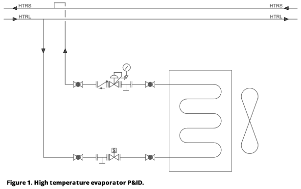
High temperature applications are frequently connected to return piping operating at +15°F (-9°C) and may include suction line inlet pressure regulators to maintain evaporating temperature above that level (Figure 1, Appendix). Addition of an in-line check valve to the return line piping will suffice to prevent reverse flow in this line. Inline check valves are available from multiple manufacturers in sizes from ½” through 8” (13mm to 200 mm) and require 0.60 - 0.75 psid (0.041 - 0.052 bard) to hold open. A low pressure drop variation is also available in sizes from 2” to 4” (50mm to 100mm) which needs only 0.25 psid (0.017 bard) to remain open. There will be no operating pressure drop penalty from the check valve spring if an inlet pressure regulator is present, as the pressure drop between evaporator and suction main must occur whether it takes place across the regulator alone or the regulator-check valve combination.
- Safety & function: This is the simplest method available; seal effectiveness depends on spring and differential pressure across the check valve ring plate.
- Installation: Weld connections permit direct insertion in return line piping and flanged connections allow for close coupling to other valves.
- Operation: 0.75 psid (0.052 bard) from an in-line check valve will mean a temperature penalty of 0.9°F (0.5°C) or ≈ 1.6% extra BHP/TR (kW/kW).
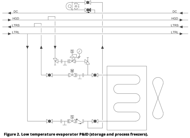
Storage freezers with a SST of -10°F to -25°F (-23°C to -32°C) will operate at suction pressures above atmospheric (9.0 to 1.3 psig, 0.62 to 0.089 bar) and typically use externally operated suction stop valves as opposed to regulators (Figure 2, Appendix). A low pressure drop in-line check valve could be used on freezers operating at the upper end of the SST range, but proper control of externally operated suction stop valves will work just as well and will eliminate operating pressure drop. High-pressure gas operated valves are available in port sizes from 1¼” to 8” (32mm to 200mm), with a majority of them held open by springs and closed by a high-pressure vapor source; one type is oppositely held open by the high-pressure gas and closed by a spring. Gas operated valves typically have metal-to-metal seats. Motorized valves are also available in port sizes from ¾” to 6” (20mm to 150mm) and may have metal-to-metal or soft seats. Motorized valves will remain at their last position if control power is lost and therefore are frequently equipped with uninterruptible power supplies (UPS) or an alternate power source to maintain control under such conditions. Finally, butterfly valves suitable for low temperature ammonia service are available in most practical port sizes and can be fitted with spring return actuators to allow the valve to close upon loss of power. Butterfly valves may also have metal-to-metal or soft seats.
- Safety & function: In-line check valve seal effectiveness depends on spring and differential pressure across the valve’s ring plate. Externally operated valves typically have more than sufficient force to achieve tight closure, hence leaks tend to be caused by foreign material trapped between the sealing surfaces or valve distortion from misaligned pipe. Any high-pressure gas operated valve must have a highpressure source available under all operating conditions to be safe and effective.
- Installation: Weld connections permit direct insertion in return line piping and flanged connections for motorized valves are available up to 4” (100mm). Butterfly valves of any port size typically require flanged connections.
- Operation: A low pressure drop (0.25 psid, 0.017 bard) in-line check valve at -10°F (-23°C) will impose a temperature penalty of 0.4°F (0.2°C) or ≈ 1.1% extra BHP/TR (kW/kW). The same valve at -25°F (-32°C) will produce a 0.6°F (0.3°C) temperature penalty or ≈ 2.0% extra BHP/TR (kW/kW). Externally operated valves have no operating pressure drop or temperature penalty.
Process freezers operating at -40°F (-40°C) or lower almost always use externally operated suction stop valves since they minimize evaporating temperature penalty. Available valve types and their safety, function and installation details are the same as discussed for storage freezer applications. Operating pressure drops due to the springs of in-line check valves makes them unsuitable for this low-temperature application, as even a pressure drop of 0.25 psid (0.017 bard) imposes a temperature penalty of 0.8°F (0.4°C) at a SST of -40°F (-40°C) and 1°F (0.6°C) at a SST of -50°F (-46°C). Since the entire suction piping temperature penalty is often desired to be no more than 2°F or 3°F (1.1°C or 1.7°C), the operating pressure drop across the spring of an in-line check valve is too great for this service.
Operations
In the process of selecting and implementing suction line controls, it is useful to examine leak scenarios at the three SST ranges previously listed. Mitigating any such scenario begins by evacuating plant personnel safely and quickly. The next step is containing and stopping the ammonia leak as soon as possible while minimizing maintenance personnel exposure to the risk of chemical attack or deflagration.
The amount of NH3 released and the risk to refrigeration operating personnel can be minimized by using the methods previously discussed to isolate a damaged evaporator. The situations described below include a baseline acceptance of loss of the evaporator’s charge, but preplanned and carefully executed action by skilled refrigeration technicians can often reduce a release to substantially below this amount. These actions become critical when dealing with evaporators larger than 30 TR, as their increased operating charges can produce ammonia concentrations that approach the lower flammability limit (LFL) and that would prevent maintenance personnel from readily responding.
- Spaces served by evaporators larger than 30 TR should be considered for use of ammonia detectors with operating ranges of 0-2% in order to accurately determine the ammonia concentration and how quickly that concentration is rising as an indication of the leak rate.
- Plants should consider placing CCTV cameras in spaces adjacent to large evaporators to maintain observation during releases that may cause hazardous ammonia concentrations.
- Post-defrost operation and/or improper startup after extended downtime or power loss are situations in which a disproportionate number of line and component ruptures occur. Many of these could be eliminated by installation of an evaporator pressure sensor to prevent opening of the automatic suction stop valve unless that evaporator pressure is below an acceptable level. Access to controls involving hot gas defrost procedures should be restricted to trained technicians, i.e., individuals with sufficient experience, training and authorization to successfully operate the system containing these controls.
All of these recommendations notwithstanding, events requiring quick and safe isolation of evaporators still occur. Most refrigeration control valve groups are located on a roof above the evaporators. System design providing automation of coil isolation will reduce the need for personnel to manually accomplish this task and the time required to do so. Increased knowledge of the building space’s conditions and ammonia concentration will prevent personnel from unknowingly being sent into or above hazardous areas.
High SST equipment operating at above atmospheric suction pressures and using suction line in-line check valves can be separated from the ammonia system by stopping all evaporator inlet flows and allowing the evaporator pressure to drop below system suction line pressure, at which point the check valve will close and prevent further ammonia from entering. Manual or semiautomatic operation of suction inlet pressure regulator control valves and/or pumpout piping may allow the evaporator pressure to be lowered and reduce the amount of charge lost to the refrigerated space. Smaller evaporators without hot gas defrost can easily use this method. Larger evaporators and more complex suction piping, particularly on PHVAC units, will require more planning from the designer as well as the operator. Fortunately, PHVAC units are usually located on the roof and much of the released charge will disperse to atmosphere instead of inside a building space.
Storage freezers and other refrigeration applications operating at SSTs of -10°F to -25°F (-23°C to -32°C) almost always use hot gas defrost and will thus require a suction stop valve controlled by high-pressure gas, an electric motor or a pneumatic actuator to isolate the evaporator from reverse suction line flow. Valves using high-pressure gas can include main control pistons with small relief holes that pass a small amount of ammonia into the space, so use of motorized globe valves or butterfly valves with electric or pneumatic actuators is preferred. As previously discussed, motorized valves typically remain at their last position when deenergized and will require a protected power source or UPS to insure safe operability under all conditions. Butterfly valve actuators also remain at their last position, but can be fitted with spring return capability which will insure that these valves modulate closed even if power is lost. Larger storage freezers frequently install evaporators of 30 TR capacity or greater in rooftop penthouses with ducted airflow into the refrigerated space. This application usually will not produce a space concentration approaching LFL unless the pipe break is catastrophic and the evaporator remains connected to live refrigerant piping for an extended duration.
Process freezers operating at SSTs of -40°F (-40°C) or lower present several notable issues when considering leak mitigation methods:
- Their large evaporator capacities tend to place substantial amounts of ammonia immediately adjacent to relatively large numbers of plant personnel.
- Leaks from process freezer evaporators remain in the freezer enclosure or the process space unless that space is cooled with PHVAC units equipped with substantial outside air capability. This makes it imperative to evacuate plant personnel quickly, but frequently prevents maintenance personnel from entering the space due to high ammonia concentrations. The extended range ammonia detectors mentioned above should be used here and in sufficient numbers to help identify the leak source.
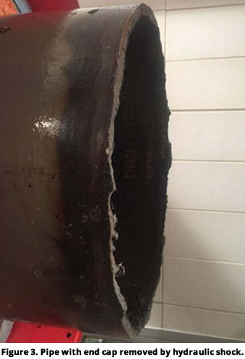
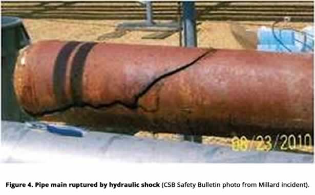
- Suction line pressure at these SSTs is below atmospheric and while that may reduce the amount of ammonia lost, it also allows air to be taken into the refrigeration system. If the line break results from a separated end cap or similar opening (Figure 3, Appendix) instead of a ruptured pipe (Figure 4, Appendix), the amount of air ingested may quickly render the condensers ineffective and lead to refrigeration system shut down. The system will then equalize at pressures above atmospheric and ammonia from the entire low temperature suction piping network can flow back into the damaged freezer evaporator.
For these reasons, it is imperative that process freezer evaporators be capable of being quickly and reliably isolated. This equipment is frequently designed with multiple evaporators so that one can be defrosted while the others remain operating, but even this approach can result in evaporators of 50 to 75 TR capacity or larger. The suction control valve isolation methods described for use in storage freezers apply also to process freezer evaporators, with butterfly valves used if port sizes larger than 6” (150mm) are required. Multiple adjacent process freezers’ pipe networks may be able to provide a trained and skilled operator with options for transferring ammonia from damaged portions of the system to a safer location if time allows. These situations are largely dependent on details particular to a given installation and thus outside the scope of this paper, but their design solutions should be closely coordinated with refrigeration operators, discussed in a Process Hazard Analysis (PHA) and possibly partially automated by controls subroutines operable only by trained and authorized technicians. These control modifications could be used to isolate single or multiple evaporators quickly and this flexibility could extend to situations involving ruptured piping mains. Evaporators thus isolated should be evaluated for overpressurization and fitted with safety relief valves (SRV) to protect all pressurized components as necessary.
Conclusions
- Ammonia evaporator leaks inside a building space pose chemical exposure and deflagration risks to maintenance personnel attempting to isolate the damaged evaporator.
- Suction line control valves can be applied to isolate evaporators operating at various SSTs with little or no evaporating temperature penalty. They are frequently part of standard designs and need only be repurposed to accomplish this function with minor control modifications.
- Larger evaporators can more easily produce ammonia releases approaching LFL, let alone levels prohibiting personnel response. Auxiliary equipment such as extended range ammonia detection and CCTV systems will provide effective situation monitoring under hazardous conditions for relatively little cost.
- Process freezers inherently create a more dangerous evaporator leak situation due to larger evaporator size and a frequently larger number of plant personnel in the immediately adjacent space. Improper defrost operation and postpower-loss startup of such equipment produce an inordinately large quantity of release incidents from this equipment. Modest additional equipment and rigorous restriction of system control to experienced, trained and authorized operators can reduce this number.
Appendix
Caylor Engineering & Associates, PLLC, is a private consulting mechanical engineering firm specializing in NH3 and CO2 Refrigeration Systems used in process and cold storage applications. Clients have included Leprino Foods, Safeway, Dreyer’s, Tyson, ConAgra, Unilever, Nestlé, Imperial Irrigation District, Lineage Logistics, and Grupo Kuo (Kekén).
©Copyright - All Rights Reserved
DO NOT REPRODUCE WITHOUT WRITTEN PERMISSION BY AUTHOR.